
“Architecture is built diagrams” (Paul Laffoley: artist, philosopher & architect)
Confronting a blank page with a mind full of ideas at the start of designing a project can be the most challenging part of the project. Getting started somewhere, anywhere, is the usual answer. Make a mark on the sheet; some lines; any lines will do to get the ideas flowing. The first few sheets of yellow trace with the tentative marks get thrown into the bin, but soon you can see those marker lines starting to take the shape of the solution.
But, how often do we spend some hours sketching, adding elements, marking workflows, adding notional major equipment items to give some structure to the sketch before moving to the computer-aided design (CAD) process and when talking the idea through with another designer and they say, “where’s the…?” and you realise that some functional space, often a secondary but essential item has been missed. Then, rather than start all over again, the sketch is adjusted to squeeze it in; potentially compromising the overall; maybe only a small compromise, but one that can be avoided by starting the design process with a functional workflow diagram.
The flow of information
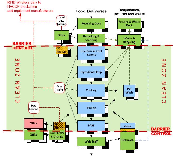
The diagram will be used to provide the basis for the actual design by identifying the operating functions and spaces and the essential relationship of each to the overall workflow of the facility. The diagramming process can also be used to identify the flow of information and data as well as the staffing and capacity requirements of the production process before the actual sketch design process starts.
The benefit of using a flow diagram to the designer is that it can be used to expand the story by identifying and more than just defined areas of the kitchen such as offices, storage and production areas. It can also be used to indicate and to link into the relevant functional spaces essential activities or particular critical items of equipment to ensure that an every essential function is included and works in the ideal location within the overall workflow.
Now the diagram is picking up all major and minor functions of the facility it can be used to define the barrier between the ‘clean’ kitchen area and the potentially ‘contaminated’ everywhere else to ensure the safety of the food production and of the kitchen staff with the Hazard Analysis Critical Control Points (HACCP) critical control points and other risks identified so that they can be resolved in the final design.
Added to the diagram can be Internet of Things (IoT) linkages; data network and security points. By layering the diagram it can also be used to define the particular mechanical ventilation, temperature and lighting levels.
If the information in a particular kitchen work area becomes complex, a secondary diagram can be broken out of the main diagram to enable it to be more clearly resolved. This workflow diagram example (below) has been made using MS Visio.
 All this information has effectively described the facility without designing it. Often clients or their staff who cannot follow or understand a layout drawing or even really understand a 3D presentation other than that it looks impressive, will be able to follow and interrogate a flow diagram: ‘Where do I do this, or that?’; ‘Why is something not next to this because I need to get to it all the time’.
The process of guiding others through the diagram will be effective in drawing out the small details that otherwise can be missed but that will make the final design fully complete.
Ideal spatial relationships
The flow chart is a brief of the functional flow of the kitchen that indicates each step of the production process and therefore the ideal spatial relationships; it is not dimensioned and therefore does not resolve how the actual spaces will be able to interconnect.
This can be left up to the drafting process but the consultant can also work through the proposed design using a scaled block diagram. Once again this can be used as a simple device to show client how the design will work.
The most important benefit of the block diagram (below) is resolving the direct interconnection of each stage of the production sequence in the most cost effective way avoiding crossing over or requiring separate passages to link the workflow. The diagram process is done by breaking the design into scaled and ideally proportioned individual functional blocks which then can be manipulated on the screen to match the requirements of the workflow diagram.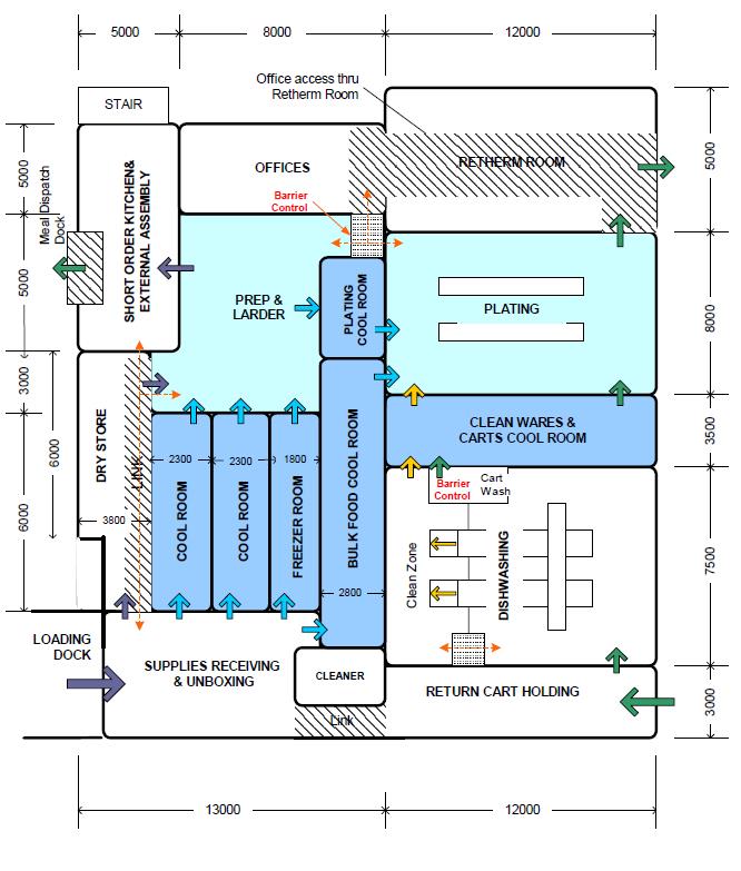
This can take time and may even show that it is not possible to deliver the ideal fully integrated workflow in the space available but it will identify the best option which can be reviewed with the client so that they understand and agree to any compromises before the process of documenting the design takes place.
The block diagram has also been built up using MS Visio dimensioned blocks; deliberately with rounded corners to show how each area butts up against the next and to avoid trying to look like a finished drawing when presenting to a client. It can be done on sketch paper or even cut out card that can be moved around and fitted together like a jigsaw.
With the flowchart and block diagram the consultant can workshop and test the ideas and concept with the client who can sign it off before even the preliminary documentation of the design commences. Once the documentation commences it will be appreciated and worked on as a resolved single end-to-end concept by those who will be working on documenting individual sections of the overall design.
As can be seen this approach to the design of a new or upgraded facility can be used effectively within the design studio to better manage a complex foodservice design. It can equally be used by clients when added to the story of their vision to be part of the brief to their consultants and designers that avoids having to use prescriptive descriptions to explain their requirements. This leaves the designer creative space for innovation.
Tim Smallwood FFCSI
